
This first section is a comment, describing what the program does. The PWM pins are identified with a "~" sign, Want to change the pin you're using, be sure to The analogWrite() function uses PWM, so if you
#Arduino analogwrite ground how to#
This example shows how to fade an LED on pin 9
#Arduino analogwrite ground code#
In the code text editor, you can see the Arduino code generated by the code blocks. Or duplicate this one (right click), and this time change it to count down, start with Either drag a new counting loop into the editor, To fade the LED back off again, we have to createĪnother counting loop. The counting loop you created fades the LED from off to all the way on.

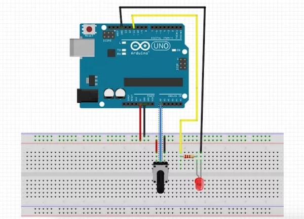
The duration of this block can be changed to slow This gives time for the light to shine at each brightness level so you have time to see itīefore it changes. Add a wait block (also in the Control category), and set it to 30 milliseconds.Output block (to replace the zero) to set pin 9 to the current value of brightness, whichĬhanges over the course of the counting loop. Navigate to Variables and drag the brightness block to the Inside the counting loop, add an analog output block "set pin to (0)", and adjust it to pin 9.Adjust the "from" and "to" values to 0 and Click the dropdown next to "for" and select "rename variable.", then Click on the Control category and drag out the "Count up by." block.The Arduino comes preloaded with the Blink sketch.You can toggle back and forth to compare the sample code with your own. Click on the Arduino Uno you added to see its code, or select it from the dropdown menu "1 (Arduino Uno R3)". While the sample circuit is selected, that Arduino Uno's code is shown in the code editor. Click the "Code" buttonto open the code blocks editor. Let's go over the simple program responsible for fading the LED, which can be built in code blocks or composed using the Arduino programming language. Connect LED anode (positive, longer leg) to Arduino pin 9.The resistor can go in either orientation because resistors aren't polarized, unlike LEDs, which must be connected in a certain way to function. Connect the LED cathode (negative, shorter leg) to one leg of a resistor (anywhere from 100-1K ohms is fine).Connect breadboard power (+) and ground (-) rails to Arduino 5V and ground (GND), respectively, by clicking to create wires.Drag an Arduino Uno and breadboard from the components panel to the workplane, next to the existing circuit.Identify the LED, resistor, and wires connected to the Arduino in the Tinkercad Circuits workplane.Since you're still getting used to the breadboard, it's useful to take a look at the free-wired version of this sample circuit. Remember that the breadboard rows are connected inside, so you can plug in components and wires to make quick temporaryĬonnections. Take a look at the circuit in the workplane.


 0 kommentar(er)
